18-DoF Biomimetic Hexapod Robot
The 18-DoF Biomimetic Hexapod is a ground-up robotics project spanning mechanical design, embedded control, and machine perception. Six legs, each with three STS3215 serial-bus servos, are coordinated by an ESP32 running inverse kinematics and tripod gait generation in real time. The near-term goal is stable walking and IMU-based balance on varied terrain. A Raspberry Pi will eventually handle object detection and basic manipulation.
Built on Waveshare's HexArth
- July 9, 2026 · 12:NaN PM
Initial brackets were printed for one leg. There were several components where the thickness was too small, resulting in difficulty with inserting the screws because of the lack of depth. The thin brackets resulted in the bracket`s being very vulnurable to buckling.
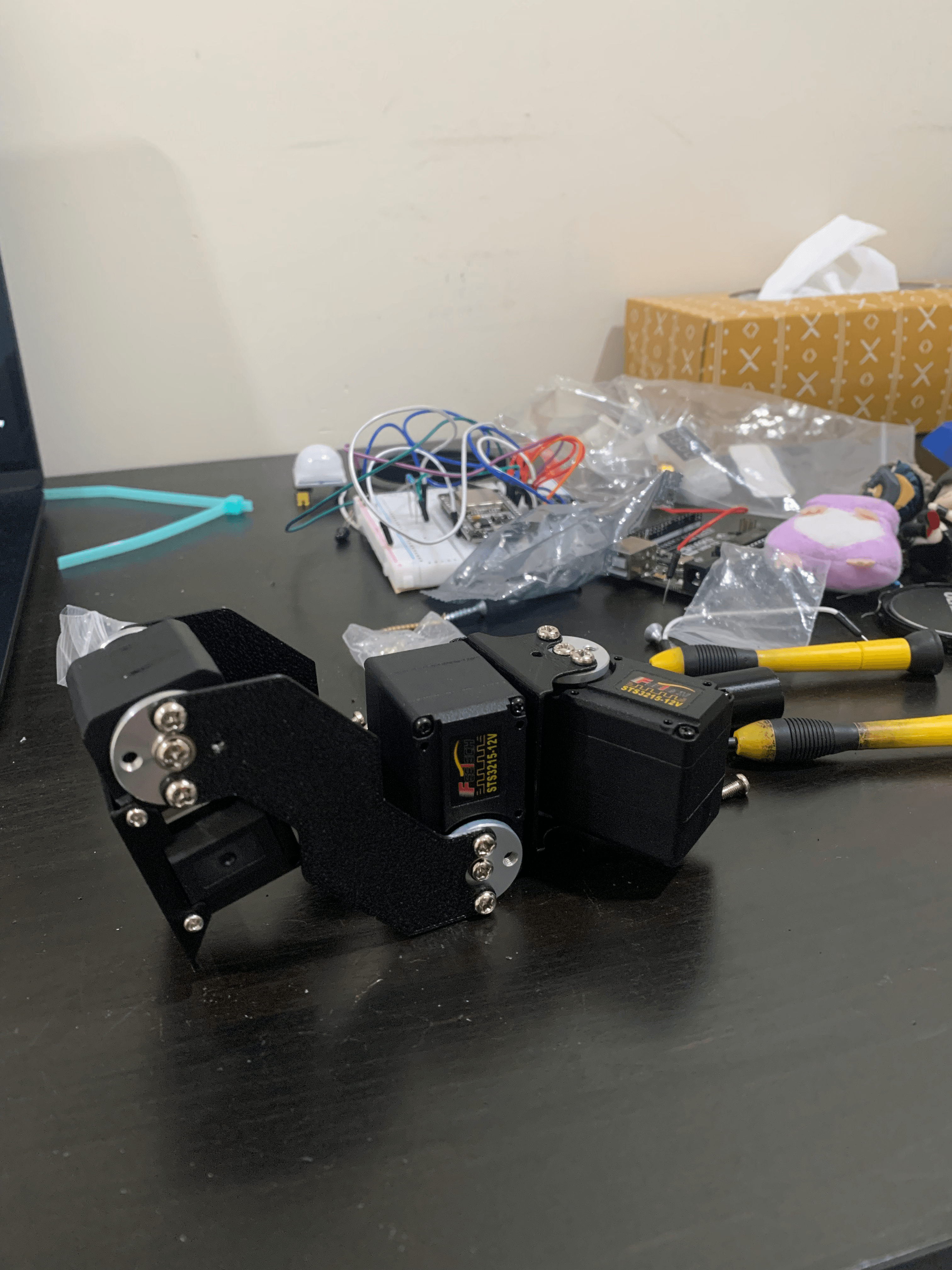
Leg assembly. - July 3, 2026 · 12:NaN PM
Some more bench testing. The ESP32 was hooked up to the STS3215 Servos, connected to an IMU. The goal was to turn the servos as the IMU rotated.
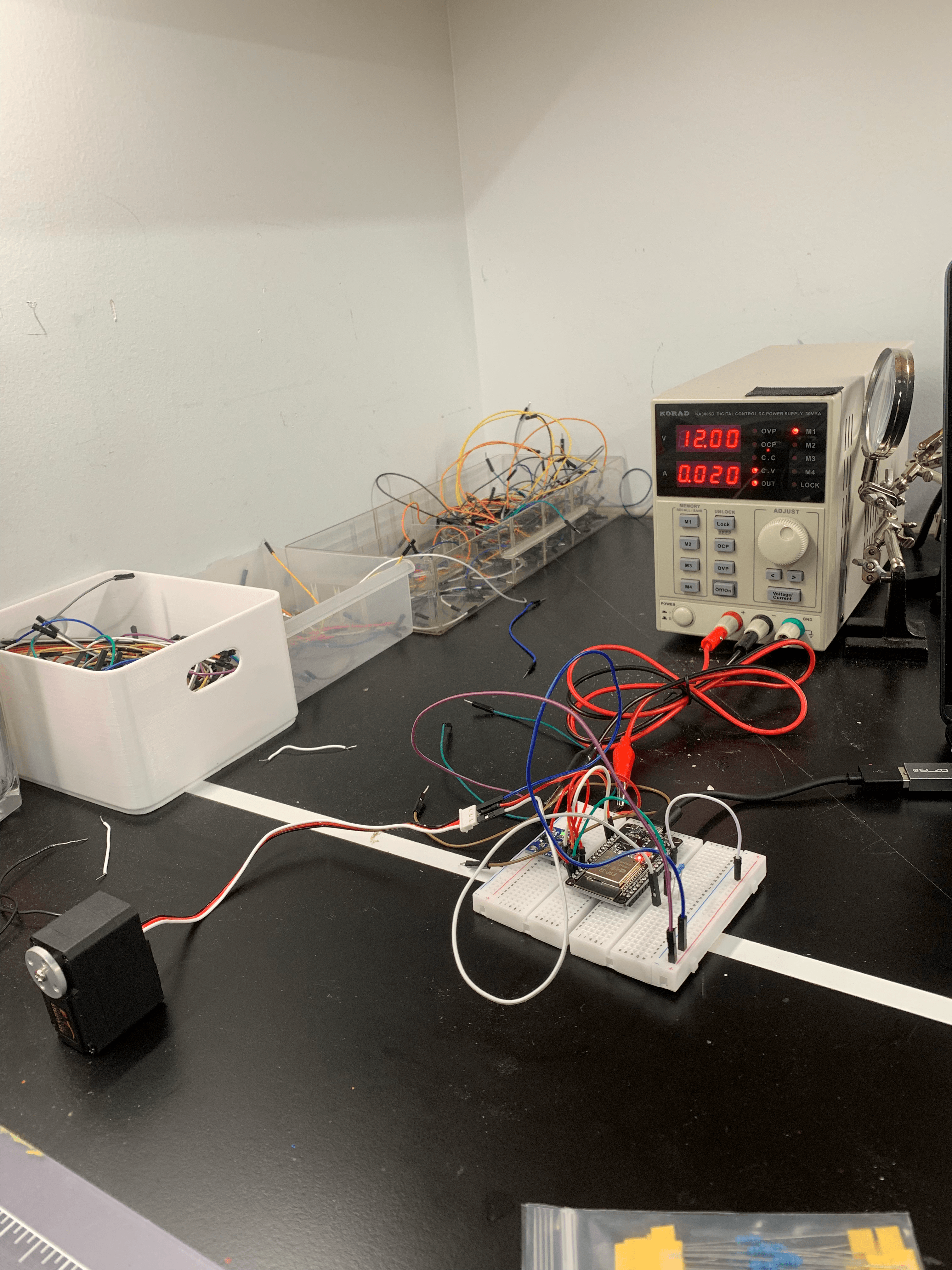
Preliminary testing. - June 27, 2026 · 3:NaN AM
A lot of testing was done this week. As I finish designing the leg brackets, along with body components, I was busy testing the STS3215 Servos. They required 12v, and I signed up for SparQ Studios in Mitchell Hall, a space with a bunch of 3D printers and power stations. I was able to get the servos moving by connecting it to a Python script, but the commands avaiable was very simple, and there was very limited functions. The reccomended method was through the SCServo library on the Arduino IDE. The next day, I used wired an ESP32 and a IMU to rotate based on its angle. Next I want to work on manufacturing the leg.
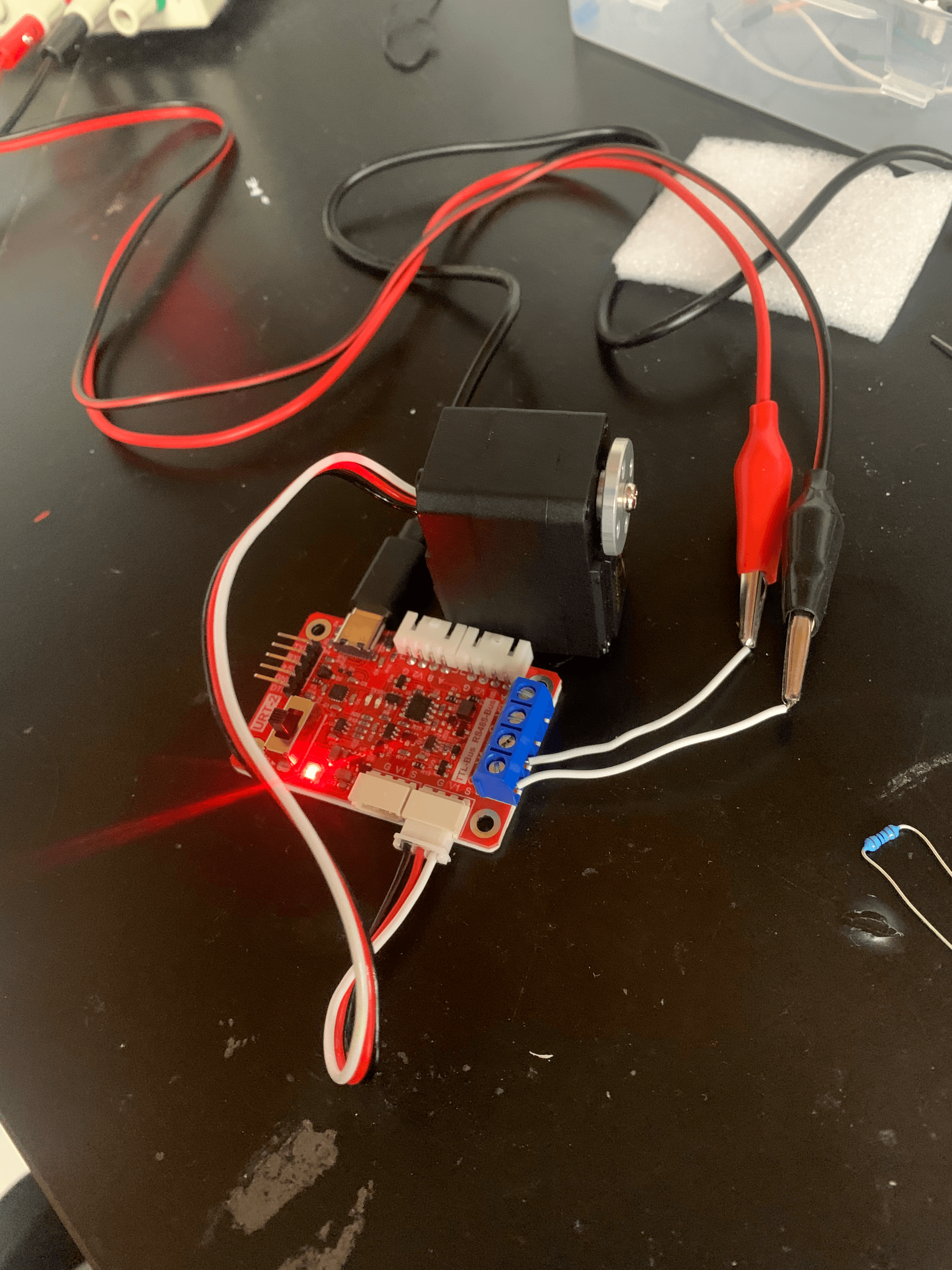
Bench testing. The URT-1 came with the servo, and I used it to assign the servo ID to 1 for simplicity. 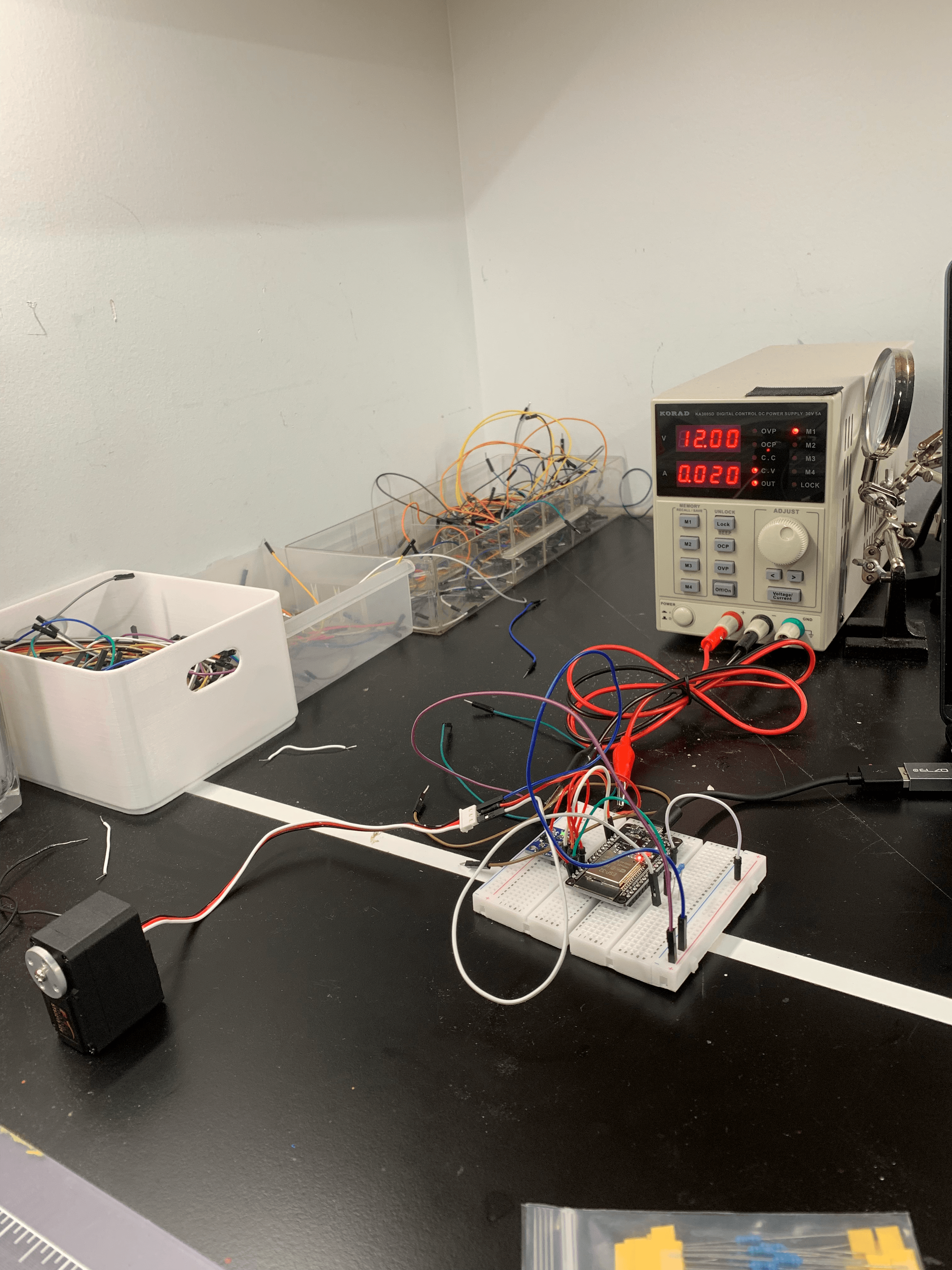
Bench testing with the ESP32. I used a IMU module to compare command rotations to the servo. - June 22, 2026 · 4:35 AM
Testing has started. The goal is to get a single leg manufactured, ensuring that the servo encoders are properly working and communcating with the ESP32. The first hurdle is supplying the 12 volts required by the servos, which I didn`t account for. I live near Queen`s University, and I will utilize their power generator to supply 12 volts for testing.
- June 5, 2026 · 11:41 AM
Today I focused on the circuit design. So as I mentioned before, the circutry should have 3 different components, the IMU, ICM, and the ESP32 (and possibly the Raspberry Pi in the future). Now, I could buy the components with a breakout board, but that wouldn`t be any fun! I will try to buy the bare chips, for the sensing units (ICM, IMU), but the esp32 I will just buy a breakoutboard to make it easier. This means that I`ll need to integrate other components that breakoutboards usually have... so much fun! the STS3215 Servos arrived, so I will test the encoder precision, and try to start printing the brackets I designed before. Thinking of getting a 3D printer, It`ll save me a few trips to the downtown library.
- June 2, 2026 · 1:24 PM
I damaged my Macbook, so I wasn`t able to work further on the Corxa-Femur brackets. I moved on to figuring out the electronics, in which I designed a schematic with 3 main components: an ESP32, INA219, and ICM-20948. For preliminary testing, the ESP32 microcontroller was selected for wifi + bluetooth capabilities, as well as being somewhat inexpensive and easy to use. The ICM-20948 sensor will be the on-board IMU (internal measurement unit) for the 3-Axis Gyro, Accelerometer, Magnetometer and temperature sensor. This IMU`s low power consumption with the breadth of data is measured makes it perfect for this project. The INA219A is a power monitor that measures bus voltage. It`ll be connected in series with the battery to measure potential voltage sags. Aside from the PCB Components, we have the LM2596 buck converter, to step down 12v from the battery to 5v for the ESP32. The battery connects to the LM2596 and the STS3125 in parallel. The 18 STS3125 will be connected through a daisy chain. Eventually, I want to add a Raspberry Pi 4 or 5 and a camera for computer vision, potentially running LLM’s for conversation, or perception models like YOLO26. For Hexapodv1, the brackets and housing will be predominantly printed in PETG, unless a component needs to be stronger during testing, in which case we can upgrade to PA6-CF or aluminium if needed. The circuitry will be soldered onto a protoboard. Game 1 tonight, go Knicks!
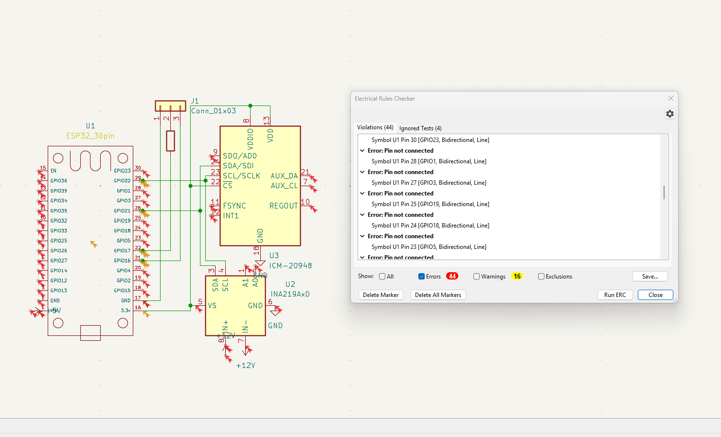
Circuit schematic for on-board electronics. 44 Errors is unheard of... I`ll need to fix those. I think the main problem is that I used Kicad raw components rather than breakout boards for the schematic design. - May 29, 2026 · 10:35 AM
I completed the leg wiring on Cirkit Designer. Ignore the weird colours, I wasn`t able to change them for some reason. Note that the FE-URT-1 (red component) is not used in the circuit. Before assembly, it will setup individual servo ID in the daisy chain.
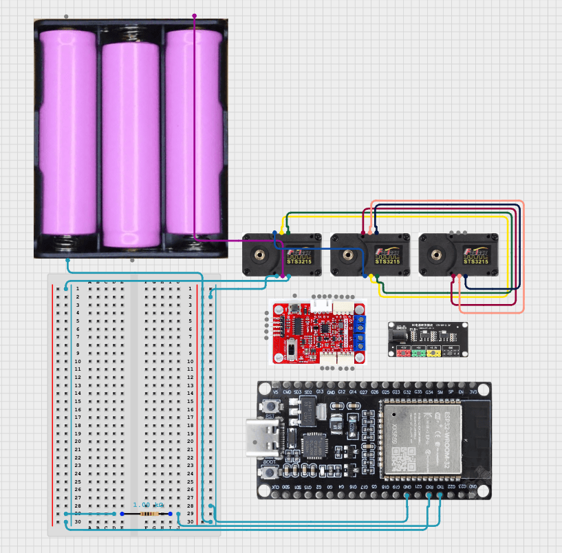
Circuit Diagram in cirkit designer. - May 29, 2026 · 12:50 AM
I finished the Corxa-Femur bracket while watching NBA Game 6 OKC vs Spurs. The Corxa will be connected to the main body of the Hexapod. Just a note for the bracket- it may be hard to 3D print, as there is a lot of overhang. The Tibia joint was improved to weight less while maintaining similar structure.
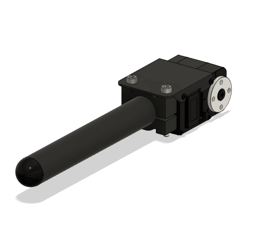
Tibia Joint with improved, lighter bracket. Changed materials to Nylon 12 and rubber for the base. 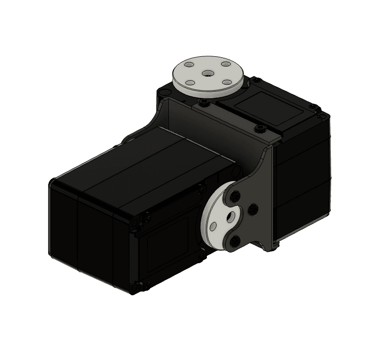
Corxal and Femur Joint bracket. - May 28, 2026 · 2:48 PM
I am going to allocate $750 to the project. The main expense is going to be the STS3215 30kg Servos for each of the legs. STS3215 Servos have magnetic rotary encoders for realtime position. The first goal is to create a 3-DoF Leg using 3 servos that serve as the Corxa, Femur and Tibia Joints. Preliminary casing model of the Tibia joint was designed in Fusion360.
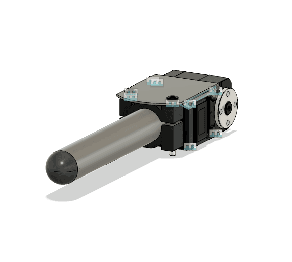
Tibia Joint with arbiturary link lengths. STS3215 Servo model from OpenCAD.